12.2. Analogue I/O
This chapter introduces the use of mPython Board pins for analog input and output. These pins are for communication with external devices when connected. The mPython Board can expand through the mPython Expansion Board I/O pins to control or read external components or modules.。
Attention
See mPython Board Pins Description , for analogue pins available details.
12.2.1. Analog Input
The available analog input pins are P0、P1、P2、P3、P4、P10, of which P4, P10 are used for control of mPython Board built-in light, Microphone sensors.
What’s analog input?
Analog input is to convert analog signal to digital signal, referred to as ADC.
To use P0 pin to read the analog input:
from mpython import *           # import mpython module

p0=MPythonPin(0,PinMode.ANALOG)     # Instantiation mPythonPin, set P0 as "PinMode.ANALOG" mode
while True:
    value=p0.read_analog()          # Read P0 pin analog
    oled.DispChar("analog:%d" %value,30,20)
    oled.show()
    oled.fill(0)
from mpython import *
p0=MPythonPin(0,PinMode.ANALOG)
Note
MPythonPin Instantiation. mode set as PinMode.ANALOG analog input mode.
Read analog unput:
p0.read_analog()
Note
Width of ADC sampling data is 12bit, the full scale is 4095。
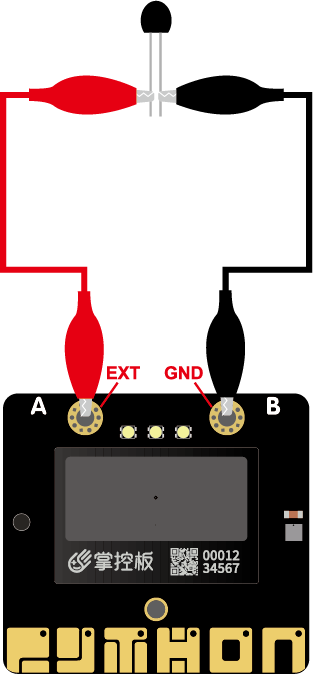
12.2.1.1. EXT Crocodile clip
Next, you can connect the resistive components (such as photosensitive and thermistor) to the EXT and GND soldering pads of the mPython Board through the alligator clip wire to measure the change of the input value of the sensor ……
EXT connection is the P3 pin on the mPython Board:
from mpython import *           # import mpython module

    p3=MPythonPin(3,PinMode.ANALOG)     # Instantiation MPythonPin, set P3 as "PinMode.ANALOG" mode
    while True:
        value=p3.read_analog()          # read EXT(P3) pin analog value
        oled.DispChar("analog:%d" %value,30,20)
        oled.show()
        oled.fill(0)
12.2.2. Analog output
What’s analog output?
Circuit board pins cannot process analog signals output of audio amplifiers - by modulating the voltage on the pins. As these pins only enable the full 3.3V output, or low level of 0V.
However, it is still possible to control the brightness of the LED or the speed of the motor by turning the voltage on and off very quickly, and to control its ON and OFF timing.
This technique is called pulse width modulation (PWM), which is the method of write_analog .
PWM signal for certain voltage output:
from mpython import *           # import mpython module

p0=MPythonPin(0,PinMode.PWM)     # Instantiation MPythonPin, set P0 as"PinMode.PWM" mode

voltage=2.0                      # 电压2V
p0.write_analog(int(voltage/3.3*1023))    #Compute the duty ratio of the corresponding voltage PWM
Note
- The
valueinwrite_analog(value)is the duty ratio of PWM signal。 - Since the I/O pin voltage is 3.3V, we need the output voltage to be 2V. Therefore, the mapping value is 2/3 * 1023.
- Since the calculated number is a floating point number, we also need to use
int()to convert to an integer.
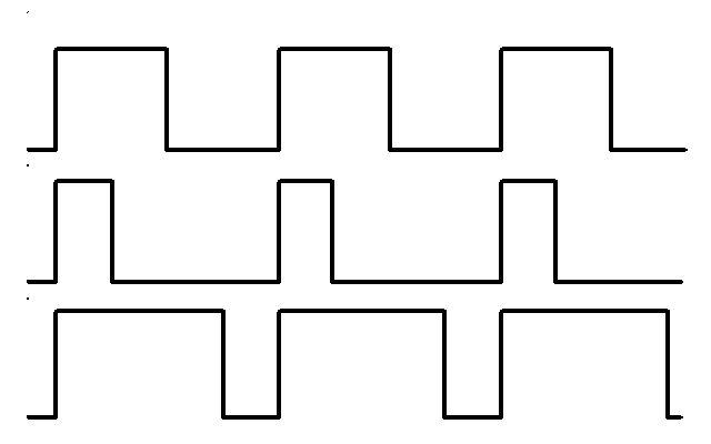
Observe three different PWM signals on the above cahrt. All have the same period (hence frequency), but with different duty ratio.
- The first one produced is
write_analog(511)because it has a duty cycle of exactly 50% - the power is in half the time and half the time. The result is that the total energy of the signal is the same, as if it were 1.65V instead of 3.3V. - The second signal has a 25% duty cycle and written as
write_analog(255). It has a similar effect as 0.825V output. - The third signal has a 75% duty cycle and can generate
write_analog(767).Its energy is three times that of the second signal, which is equivalent to output 2.475V on the second pin.