11. Serial Port
11.1. Basic concept of serial port
11.1.1. Serial port principle
The English abbreviation for serial communication is UART, which stands for Universal Asynchronous Receiver Transmitter. It is an advance concept, as shown in the figure below, two devices are connected in a line, and the sender’s online end converts the data into a binary sequence, using high and low levels to send 01 signals in sequence, and the receiver’s online another Read the high and low level signals on this signal line at one end, corresponding to the 01 sequence of binary conversion. Asynchronous sending and receiving refers to full-duplex transmission, that is, sending data and receiving data at the same time. The two are synchronized. Just like our phones, we can hear each other’s voices while talking.
Whenever we want to communicate between a PC and an MCU or between two MCUs, the easiest way is to use UART. Only two wires are required to transfer data between two UARTs. Data flows from the Tx pin of the sending UART to the Rx pin of the receiving UART.
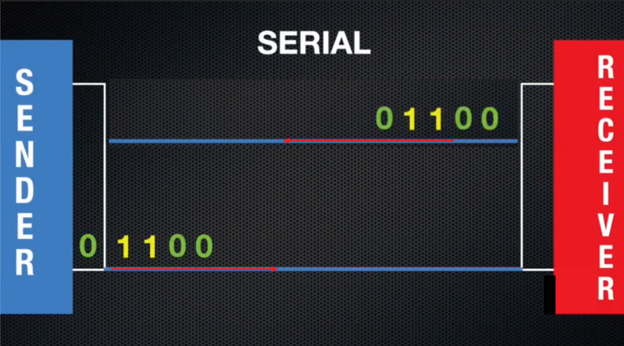
Principle of serial communication
11.1.2. Baud rate
Baud rate (baudrate) refers to the number of bits transmitted by our serial communication per second. In layman’s terms, it is how many binary numbers of 1 and 0 can be sent in one second. For example, a baud rate of 9600 means that 9600 secondary sequences consisting of 0 and 1 can be sent in 1S.
11.1.3. TX at the transmitter and RX at the receiver
UART communication basically uses 2 pins for data transmission. Tx-pin for sending of data, Rx-pin for receiving of data. For two serial ports to communicate, at least three wires are required to connect.
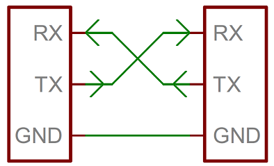
RX stands for information receiving end, TX stands for information sending end
Attention
If some modules are connected, the module does not have its own power supply, and it needs to connected to VCC!
11.2. Serial port operation
The following communicates with the serial port of the Blue:bit Bluetooth slave module through the mPython Board to finally realize the BT communication function of the mPython Board.
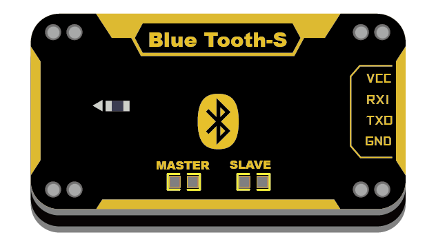
blue:bit BT module
11.2.1. construct UART
from mpython import *                            # import all mPython object

uart=UART(1,baudrate=9600,tx=Pin.P15,rx=Pin.P16) # construct UART object,set Baud Rate at 9600,the TX、RX pins are P15、P16 respectively.
HC06(blue:bit BT slave module) The default factory baud rate is 9600. Need to use the factory default setting baud rate of 9600. Then based on your needs of the connecting serial port to set the baud rate.
UART(id, baudrate, bits, parity, stop, tx, rx, rts, cts, timeout) , id is the serial port number, which can be set as 1 ~ 2. The mPython Board had 3 groups of serial ports, which 0 had been allocated for REPL.
baudrate is parameter for Baud Rate, tx is the mapping pin on mPython Board for sending, rx is the mapping pin for receiving. All pins can be used as serial port input RX, except `` P2``, `` P3``, `` P4``, `` P10`` can only be used as input, theoretically all other pins can be used as output TX. Generally, only the above parameters need to be set, and other parameters will remain the default parameters. For more UART parameters, refers to machine.UART chapter.
11.2.2. Serial port transmission
Use a Bluetooth-enabled computer or mobile phone to download the Bluetooth debugging assistant for BT module pairing. As such to realize the transmission of the mPython Board to the computer/mobile phone.
After successful pairing, send byte data to the serial port:
>>> uart.write('hello,world!')
Then, use the serial port assistant to check if received the data from the mPython Board. The uart.write(buf) function writes (sends) byte data to the serial port and returns the length of the data.
11.2.3. Serial port reading
The mPython Board receives serial data and displays the data on the OLED screen:
from mpython import *                               # Import all mpython object

uart=UART(1,baudrate=9600,tx=Pin.P15,rx=Pin.P16,timeout=200)    # Example UART, set baud rate 9600, TX, RX mapping pins are P15, P16, timeout is set to 200ms

while True:
    if(uart.any()):                     # When the serial port has readable data
        data = uart.readline()          # Read a line of data from the serial port
        print("received:",data)         # Print received data
        oled.DispChar("接收:%s" %data.decode('utf-8'),0,30)     # Display data on the OLED, pay attention to the need to decode the bytecode into a string
        oled.show()                     # take effect
        oled.fill(0)                    # clear screen
Now, you can send data to the serial port through the serial assistant, when the control panel receives the serial data, print and display it to the OLED screen. In the while loop, polling uses uart.any() to determine whether there is readable data in the serial port. When there is data, use uart.readline() read a line of data. It should be noted that the serial port receives the byte type. If it is transmitted to the OLED display, you need to use decode() to convert the byte to a string.
In addition to UART.readline() to read data, you can also use UART.read(length) to read data of specified length from the serial.
11.3. Expansion
After learning how to use the serial port, you can realize the communication between the control board and other MCU (Arduino), computer / mobile phone, electronic module. With more extensive application, imagine and use the serial port and with your imagination to build and create more interesting things!