Hardware Overview
The mPython Board is a MicroPython microcontroller board with full support for MicroPython/Python software features.
Technical Specification
mPython Board had the following hardware features:
- ESP-32 microcontroller
- Processor:Tensilica LX6 dual core microprocessor(one for Handling High Speed Connections and the other for Independent Application Development)
- Main frequency: up to 240mhz clock frequency
- SRAM:520KB
- Flash:8MB
- Wi-Fi Standard:FCC/CE/TELEC/KCC
- Wi-Fi Alliance:802.11 b/g/n/d/e/i/k/r (802.11n,high speed 150 Mbps),A-MPDU and A-MSDU packed,support 0.4us protective interval
- Frequency Range:2.4~2.5 GHz
- BlueTooth Protocol:Comply to BlueTooth 4.2 BR/EDR and BLE standard
- Bluetooth Audio Streaming:CVSD and SBC audio low power:10uA
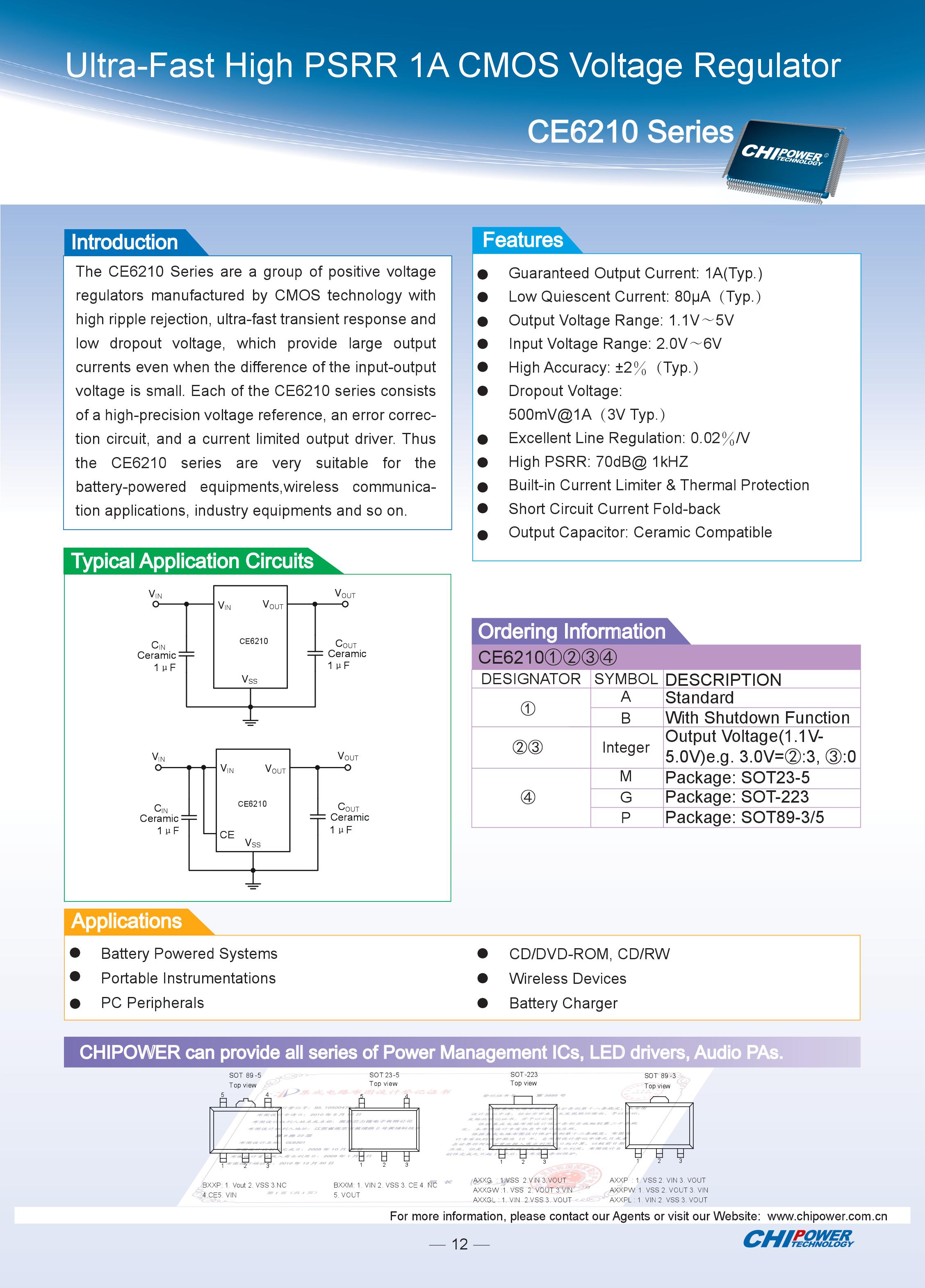
- Power Supply Mode:Micro USB
- Operating Voltage:3.3V
- Maximum Operating Current:200mA
- Maximum Load Current:1000mA
- mPython Board integrated hardwares
- 3-axis Accelerometer MSA300, Range: ±2/4/8/16G
- Deomagnetic Sensor MMC5983MA, Range: ±8 Gauss; Accuracy 0.4mGz, Electronic Compass error ±0.5°
- Light Sensor
- Microphone
- 3x ws2812 LED, RGB
- 1.3” OLED Panel,support 16*16 characters display,Resolution 128x64
- Passive Buzzer
- Supports 2x tact switch (User A/B), 1x Reset Button, 6x Touch Button
- Supports 1x crocodile clip interface: resistive sensor input
- Interface for external device expansion
- 20x digital I/O, (it supports 12x PWM,6x Touch Pad)
- 5x 12bit ADC,P0~P4
- 1x external hardware input via crocodile clip interface :EXT/GND
- supports I2C、UART、SPI communication protocol
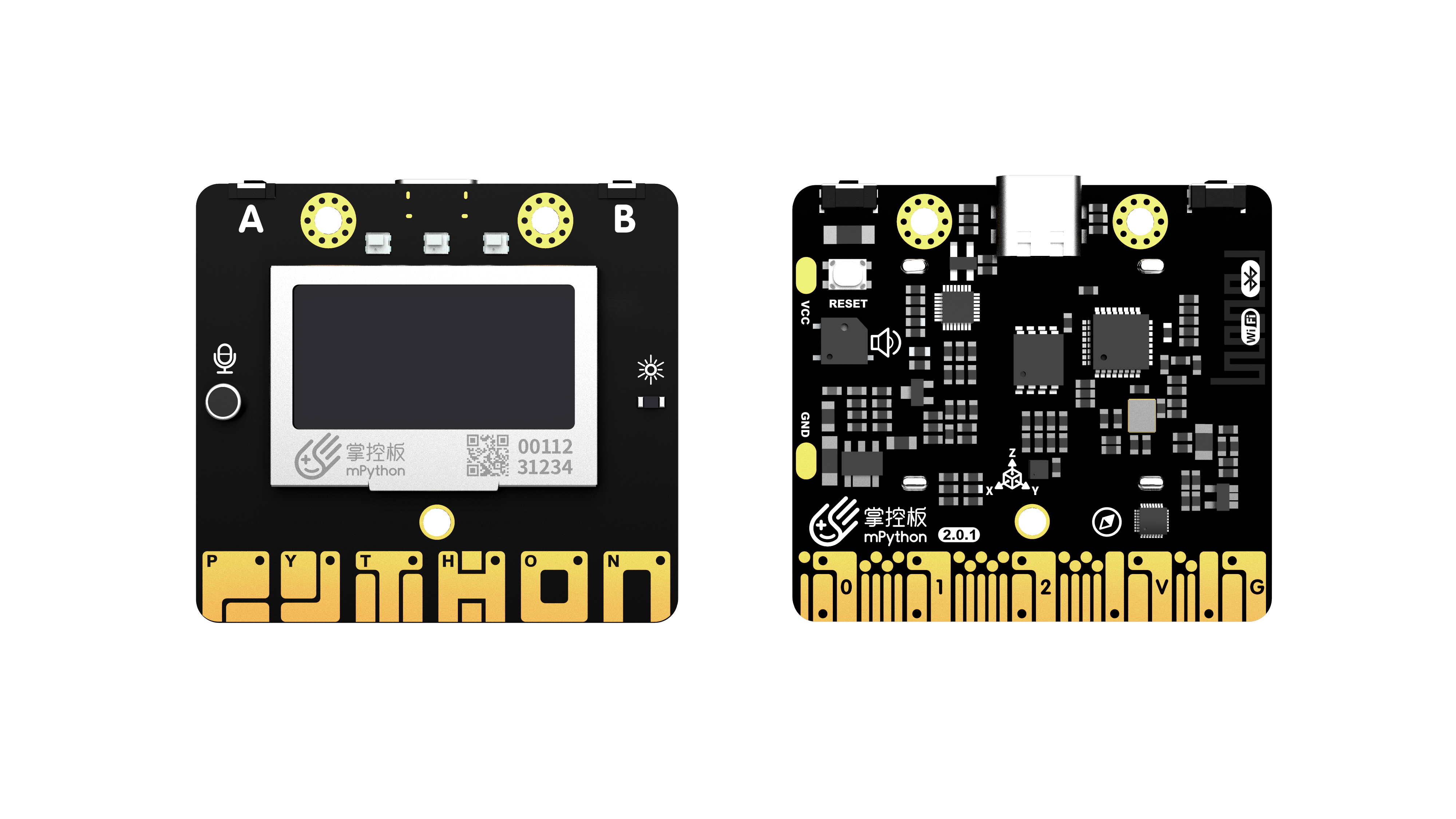
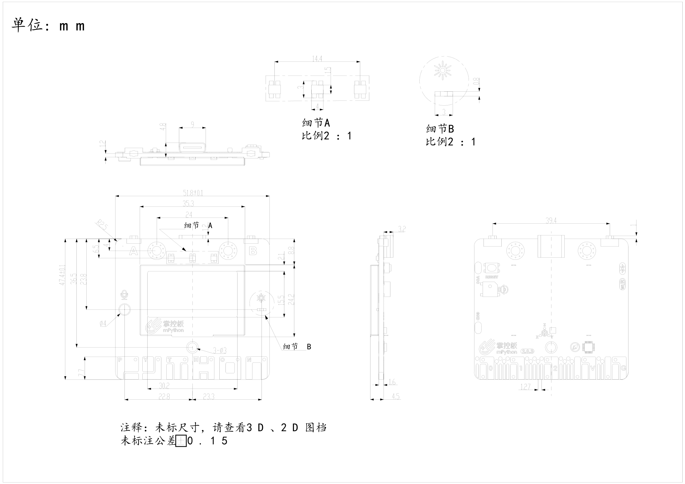
Dimension and Layout
Component Layout / Pin Definition

mPython Board interface pin configuration
| PIN | Type | Description |
| P0 | I/O | Analogue/Digital Input, Analogue/Digital Output, TouchPad |
| P1 | I/O | Analogue/Digital Input, Analogue/Digital Output, TouchPad |
| P2 | I | Analogue/Digital Input |
| P3 | I | Analogue/Digital Input, connects the Crocodile Clip slot on the Board for external passive sensor input. |
| P4 | I | Analogue/Digital Input, connects the Light Sensor on the Board |
| P5 | I/O | Digital Input, Analogue/Digital Output, connects the USER Button A on the Board, neopixel |
| P6 | I/O | Digital Input, Analogue/Digital Output, connects the Buzzer OR as Digital I/O, neopixel |
| P7 | I/O | Digital Input, Analogue/Digital Output,connects the RGB LED on the Board |
| P8 | I/O | Digital Input, Analogue/Digital Output, neopixel |
| P9 | I/O | Digital Input, Analogue/Digital Output, neopixel |
| P10 | I | Analogue/Digital Input, Analogue/Digital Output, connects the Sound Sensor on the Board |
| P11 | I/O | Digital Input, Analogue/Digital Output, connects the USER Button B on the Board, neopixel |
| P12 | I/O | NC |
| P13 | I/O | Digital Input, Analogue/Digital Output, neopixel |
| P14 | I/O | Digital Input, Analogue/Digital Output, neopixel |
| P15 | I/O | Digital Input, Analogue/Digital Output, neopixel |
| P16 | I/O | Digital Input, Analogue/Digital Output, neopixel |
| 3V3 | POWER | Power input via USB: Board regulated output: 3.3V, OR 2.7 ~ 3.6V supply via non-USB mode |
| P19 | I/O | Digital Input, Analogue/Digital Output, I2C bus SCL, with OLED and accelerometer to share I2C bus, neopixel |
| P20 | I/O | Digital Input, Analogue/Digital Output, I2C bus SDA, with OLED and accelerometer to share I2C bus, neopixel |
| GND | GND | Power GND |
| Touch_P(P23) | I/O | TouchPad |
| Touch_Y(P24) | I/O | TouchPad |
| Touch_T(P25) | I/O | TouchPad |
| Touch_H(P26) | I/O | TouchPad |
| Touch_O(P27) | I/O | TouchPad |
| Touch_N(P28) | I/O | TouchPad |