6. Motor Drive Servo
6.1. Servo Principal
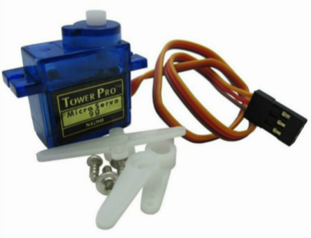
The steering gear is a position (angle) servo driver, which is a set of automatic control system composed of DC motor, reduction gear set, sensor and control circuit. By sending a signal to specify the rotation angle of the output shaft, generally speaking, there is a maximum rotation angle (such as 180 degrees). The difference from the ordinary DC motor is that the DC motor rotates in a circle, and the servo can only rotate within a certain angle , Can not turn around in one circle (but the digital servo can be switched between servo mode and motor mode). Ordinary DC motors cannot feed back the angle of rotation information, whereas servo have this unique function.
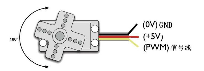
Standard Servo comes with a 3 wires cable, they are:GND (Brown)、Vcc(Red)、Signal line (Orange).
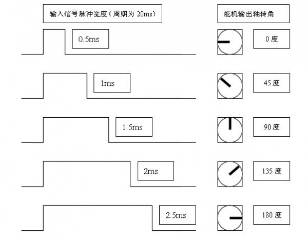
The steering gear of the servo system is controlled by pulses of variable width, and the control line is used to transmit pulses. Pulse parameters have minimum, maximum, and frequency. Basically, the reference signal period of the servo is 20ms, and the width is 1.5ms. The position defined by this reference signal is the middle position, and the angle is generated by the continuous pulse from the control line. The high level pulse is the angle control pulse part, range of 0.5ms-2.5ms, with a total interval of 2ms. This control method is called pulse modulation, and the length of the pulse determines how much the servo turns.

For example: 1.5 ms pulse will turn to the middle position (its at 90° position for a 180° servo ). When the control system issues a command to move the servo to a certain position and keep him at this angle, the effect of external forces will not change his angle, but this is from the upper limit, which is his maximum torque. Unless the control system continuously pulses to stabilize the angle of the servo, the angle of the servo will not remain constant.
The control relationship corresponding to the 180 degree angle servo is:
Attention
The range of pulse width of different servos will be different, please pay attention when controlling!
6.2. Servo acceleration control
Integrate the accelerometer to make a control angle by tilting the control panel left and right:
from mpython import *
from servo import Servo

myServo=Servo(0,min_us=500, max_us=2500)      # construct Servo object

while True:
    y=accelerometer.get_y()          #Get Y axis acceleration
    if y<=1 and y>=-1:
        angle=int(numberMap(y,1,-1,0,180))    #Map Y axis acceleration value
    myServo.write_angle(angle)       #Write servo angle
    oled.DispChar("angle:%d" %angle,40,25)
    oled.show()
    oled.fill(0)
    sleep_ms(10)
The servo and the mPython Board requires the expansion board to connect. See mPython Board port pin manual , to understand the available pins for PWM analog output. Use Pin P0. Insert the mPython Board on the expansion board, connect the servo and the expansion board through the dual female Dupont cable, and the Vcc (red) on the servo is connected to the power port “V” of the expansion board. Wire GND (brown) connects to the ground port “G” of the expansion board, and the signal wire (orange) connects to the pin “0” of the expansion board.

First,import mpython、servo module:
from mpython import *
from servo import Servo
Construct Servo object, Set the servo pulse width parameter:
myServo=Servo(0,min_us=500, max_us=2500)
Note
Servo(pin, min_us=750, max_us=2250, actuation_range=180) used to construct Servo objects, using SG90 servo by default. Different servos have different pulse width parameters and angle ranges, to set according to the servo model. pin , set the servo control PWM signal pin, min_us , set the minimum width of the servo PWM signal pulse width, in microseconds, default min_us=750,max_us , set the minimum width of the servo PWM signal pulse width, in microseconds, default max_us=2250,actuation_range sets the maximum angle of rotation of the servo.
Attention
Set the actuation_range to apply the actual motion range values observed for min_us and max_us . Observe the actual range of motion. You can also extend the pulse width above and below these limits. The servo mechanism may stop, buzz, and absorb additional current when stopped. Test carefully to find the safe minimum and maximum.
When it is detected that the mPython Board is tilted in the Y-axis direction (range -1g to +1g), the acceleration value of the Y axis (range -1 to 1) is mapped to the rotation angle of the servo output shaft (range 0 to 180):
if y<=1 and y>=-1:
    angle=int(numberMap(y,1,-1,0,180))
Output servo angle and display on OLED display:
myServo.write_angle(angle)       #Write servo angle
        oled.DispChar("angle:%d" %angle,40,25)
        oled.show()